Contact Resistance Concept
(download
PDF version)
Summary: The thermal resistance concept is frequently used for calculating heat transfer through solids. The physical significance of this concept and its application in the analysis of heat flow through composite layers are discussed. In this module we develop the thermal resistances associated with heat flow through a plane wall.
Consider two solids, each having a plane flat surface, brought together and one surface pressed against the other. The actual direct contact between the surfaces takes place at only a limited number of spots because the surfaces are not perfectly smooth but posess some micro roughness; as a result, the surfaces are not in perfect thermal contact. The voids between the surfaces are filled with the surrounding fluid, which usually is the air. The heat flow across such an interface takes place by conduction both through the thin fluid layer filling the voids and through the spots in direct metal-to-metal contact. Since the thermal conductivity of the air is less than that of metal the thin layer of air filling the voids acts as a thermal resistance to heat flow. Since this resistance is confined to a very thin layer between the surfaces, it is called thermal contact resistance.
Figure 1 illustrates the thermal contact resistance concept and the temperature profile through the solids.
There is a sudden drop in temperature across the interface. Unless the two metals are welded, there is always a thermal resistance across such an interface. The magnitude of this thermal resistance depends on the surface roughness, the type of material, the interface pressure, the interface temperature, and the type of fluid filling the voids. A considerable amount of experimental work in predicting thermal contact resistance has been done. The inverse of thermal contact
resistance is called the interface thermal contact conductance, which has the dimensions of
(W/m2-°C). Figure 2 illustrates the effects of surface roughness, the interface pressure, and interface temperature on the thermal contact conductance for a stainless steel-to-stainless steel joint with air as the interface fluid.
The contact conductance increases with increasing interface pressure, increasing interface temperature, and decreasing surface roughness. If an aluminum-to-aluminum joint were used instead of the stainless steel joint, the contact conductance would be higher, because aluminum is softer than steel and allows more direct contact between the surfaces. Experimental data for conduction, such as those shown in
Figure 2, for different surface roughnesses and different combinations of metals are available in the literature.
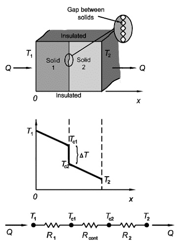
Figure 1: The concept of thermal resistance.
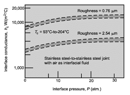
Figure 2: Effect of the interface pressure, contact temperature and roughness on interface conductance.
Examples
Example 1:
Consider two stainless steel blocks (k=20 W/m -°C) each having a thickness of 1 cm, length of 8 cm, and width of 6 cm, that are pressed together with a pressure of 20 atm. The surfaces have a toughness of about 0.76 µm. The outside surfaces of the blocks are at 120 °C and 70 °C. Calculate
- the heat flow rate across the blocks
- the temperature drop at the interface.
Solution Part 1. The total heat flow rate Q across the blocks is determined by the approximation of the thermal resistance concept:
Equation 1
Q = ΔT / (R1 + Rc + R2)
where Q is Watts and ΔT= T1 - T2 =120-70=50°C . The thermal resistances of the blocks are equal, and they are determined by:
Equation 2
R1 = R2= L / A x k= 0.01 / 20×0.08×0.06
= 0.1042 °C/W
The contact conductance of the interface is determined from Figure 2. For a mean interface temperature of
Tm = (120+70)/2 = 90°C , a surface roughness of 0.76 µm, and interface pressure of 20 atm, the contact conductance becomes
hc =10,000 W/m2-°C . Then the thermal contact resistance of the interface is given by:
Equation 3
Rc= 1 / A x h = 1 / (110,000×0.08×0.06) = 0.0208 °C/W .
Then the heat flow rate across the blocks is
Equation 4
Q = 50 / (0.1042+0.02083+0.1042) = 218 Watts
Solution Part 2. The temperature drop across the interface becomes
Equation 5
ΔTc =ΔT x Rc / (R1 + Rc + R2)
=50 x (0.0208 /( 0.1042+0.0208+0.1042)) = 4.54°C
|