Multi-Layer Insulation (MLI)
When a simple coating is insufficient to avoid great heat losses or gains for a
surface, multi-layer insulation can be used. It consists (Figure 1) of a certain
number of layers of plastic material (normally Mylar or Kapton) coated on one or
both sides with a layer of metallic material to reduce the radiation, and
separated by sheets of spacer material (e.g. Dacron net) to avoid direct contact
between adjacent foils. The external foil coating depends on the particular
application: it can be painted, vapor deposited, metallic, or can even
consist of a different material (e.g. glass-reinforced cloth).
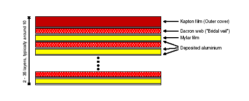
Figure 1. Typical MLI Layup
MLI efficiency can be defined either in terms of
the linear conductance through the blanket, or via the so-called 'effective
emittance'. In the first case, the thermal flux can be calculated as the
product of the given value times the temperature difference between the external
layer and the hardware covered by the blanket. In the second case, it is
calculated as a radiative heat exchange using the effective emittance (Fig. 2).
This parameter has a very simple mathematical formulation, but it can have quite
different physical meanings and the choice of definition depends on the
modelling technique used.

Figure 2. Effective-emittance definition for various MLI layouts
The factors affecting the efficiency are the
physical composition of the blanket (number of layers, type of coatings,
physical size, etc.), the average blanket temperature (usually the arithmetic
mean between the two outermost layers), the eventual presence of air or humidity
within the layers, and the pressure between them. A very important factor is
the way in which the blanket is applied to the spacecraft surface: a single
piece of blanket covering a large surface is more efficient than a number of
small blankets covering the same surface. A blanket suspended over a surface
(case 3 of Fig. 2) is more efficient than one in direct contact with the surface
(case 1 of Fig. 2).

Generally speaking, the MLI's efficiency is
measured on relatively small samples, while the real efficiency of an MLI system
is only known at the time of system-level thermal testing. Consequently,
suitable safety factors have to be applied during the design phase.
Overlapping Seams with 15+
Layers: .015 > e* > .005
Typical Values for large surfaces:
.03 > e* > .015
Typical Values for small surfaces:
.09 > e* > .05
From JWST Study: To better appreciate the thermal attenuation performance required, consider the following
comparison with multilayer insulation (MLI) systems commonly used in space applications. The parameter typically used to characterize the performance of multilayer insulation is the effective emittance
e*, derived from Stefan-Boltzmann's law,
Q = SIGMA x e* x As x F1-2 x (T14-T24)
where Q is the heat flux transferred between the sun-side shield layer at temperature
T1 and the cold-side layer at T2, As is the
surface area, F1-2 is the view factor and SIGMA is the Stefan-Boltzmann constant. The lower the effective
emittance, the better the isolation provided by the sunshield. The required effective emittance for the NGST sunshield is around 0.0003. Typical spacecraft MLI blankets only
achieve effective emittances in the range of 0.05 to 0.007, and under ideal circumstances (no conduction between layers) no lower than 0.001.
e* = ( 2n / emylar - n - 1 + 1/e1 +
1/e2 )-1
where n = number of mylar layers, emylar
= .03 is the emissivity of mylar, e1
and e2 are the emissivity
of surfaces 1 and 2. Even if conduction between the layers is
ignored, adding additional layers to achieve the required effective emittance is impractical due to weight and packaging considerations. Furthermore, since the effective emittance is a
function of the reciprocal of the number of layers, adding additional layers becomes increasingly less effective with the number of layers, as shown in
the figure below.

In order to achieve the required effective
emittance, the shield needs to be
configured such that energy is allowed to escape to space from between the layers before reaching the
cold-side layer. As the example case in the figure above shows, this approach allows the number of layers to be greatly reduced. It is this approach of enabling the loss of energy out from between film layers which provides the required low effective emittance and makes it possible to passively cool to very low temperatures.
|